By vsara90 on
Wednesday, February 3, 2010
Helix antennas have a very distinctive shape, as can be seen in the following picture.
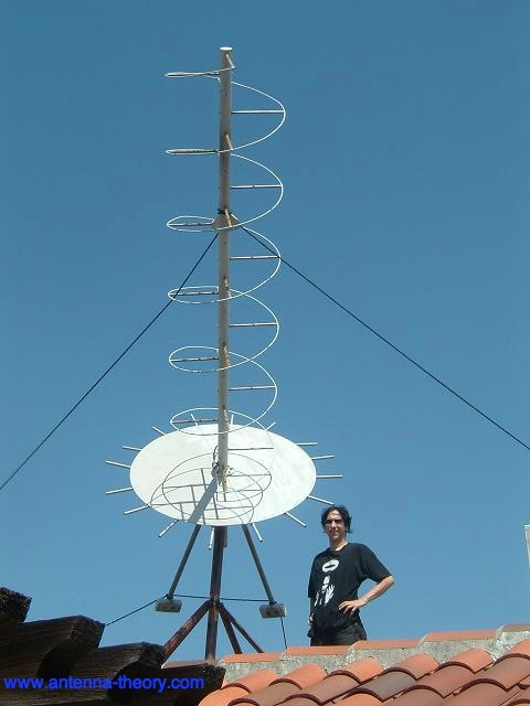 Photo courtesy of Dr. Lee Boyce. The most popular helical antenna (often called a 'helix') is a travelling wave antenna in the shape of a corkscrew that produces radiation along the axis of the helix. These helixes are referred to as axial-mode helical antennas. The benefits of this antenna is it has a wide bandwidth, is easily constructed, has a real input impedance, and can produce
 circularly polarized
fields. The basic geometry is shown in Figure 1.
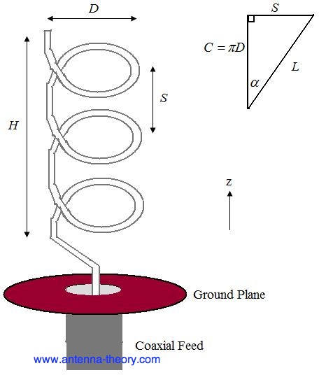 Figure 1. Geometry of Helical Antenna. The parameters are defined below.
D - Diameter of a turn on the helix.
C - Circumference of a turn on the helix (C=pi*D).
S - Vertical separation between turns.
 - pitch angle, which controls how far the antenna grows in the z-direction per turn, and is given by
N - Number of turns on the helix.
H - Total height of helix, H=NS. The antenna in Figure 1 is a left handed helix, because if you curl your fingers on your left hand around the helix your thumb would point up (also, the waves emitted from the antenna are Left Hand Circularly Polarized). If the helix was wound the other way, it would be a right handed helical antenna.
The pattern will be maximum in the +z direction (along the helical axis in Figure 1). The design of helical antennas is primarily based on empirical results, and the fundamental equations will be presented here.
Helices of at least 3 turns will have close to circular polarization in the +z direction when the circumference C is close to a wavelength:
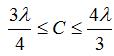 Once the circumference C is chosen, the inequalites above roughly determine the operating bandwidth of the helix. For instance, if C=19.68 inches (0.5 meters), then the highest frequency of operation will be given by the smallest wavelength that fits into the above equation, or
  =0.75C=0.375 meters, which corresponds to a frequency of 800 MHz. The lowest frequency of operation will be given by the largest wavelength that fits into the above equation, or =1.333C=0.667 meters, which corresponds to a frequency of 450 MHz. Hence, the fractional BW is 56%, which is true of axial helices in general.
The helix is a travelling wave antenna, which means the current travels along the antenna and the phase varies continuously. In addition, the input impedance is primarly real and can be approximated in Ohms by:
 The helix functions well for pitch angles () between 12 and 14 degrees. Typically, the pitch angle is taken as 13 degrees.
The normalized radiation pattern for the E-field components are given by:
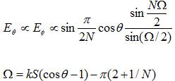 For circular polarization, the orthogonal components of the E-field must be 90 degrees out of phase. This occurs in directions near the axis (z-axis in Figure 1) of the helix. The axial ratio for helix antennas decreases as the number of loops N is added, and can be approximated by:
 The gain of the helix can be approximated by:
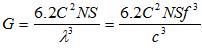 In the above, c is the speed of light. Note that for a given helix geometry (specified in terms of C, S, N), the gain increases with frequency. For an N=10 turn helix, that has a 0.5 meter circumference as above, and an pitch angle of 13 degrees (giving S=0.13 meters), the gain is 8.3 (9.2 dB).
For the same example helix, the pattern is shown in Figure 2.
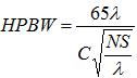
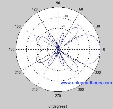 Figure 2. Normalized radiation pattern for helical antenna (dB). The Half-Power Beamwidth for helical antennas can be approximated (in degrees) by:


Post a Comment