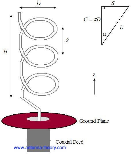
 Figure 1. Geometry of Helical Antenna.
 - pitch angle, which controls how far the antenna grows in the z-direction per turn, and is given by
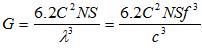
The pattern will be maximum in the +z direction (along the helical axis in Figure 1). The design of helical antennas is primarily based on empirical results, and the fundamental equations will be presented here.
Helices of at least 3 turns will have close to circular polarization in the +z direction when the circumference C is close to a wavelength:
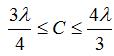
 =0.75C=0.375 meters, which corresponds to a frequency of 800 MHz. The lowest frequency of operation will be given by the largest wavelength that fits into the above equation, or =1.333C=0.667 meters, which corresponds to a frequency of 450 MHz. Hence, the fractional BW is 56%, which is true of axial helices in general.
The helix is a travelling wave antenna, which means the current travels along the antenna and the phase varies continuously. In addition, the input impedance is primarly real and can be approximated in Ohms by:
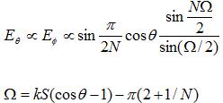
 ) between 12 and 14 degrees. Typically, the pitch angle is taken as 13 degrees.
The normalized radiation pattern for the E-field components are given by:

For the same example helix, the pattern is shown in Figure 2.
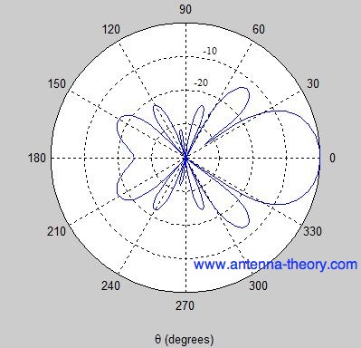 Figure 2. Normalized radiation pattern for helical antenna (dB).
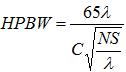
The Short Dipole Antenna
The short dipole antenna is the simplest of all antennas. It is simply an open-circuited wire, fed at its center as shown in Figure 1.
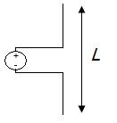 Figure 1. Short dipole antenna of length L.
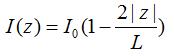
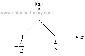 Figure 2. Current distribution along a short dipole.
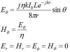
 and
and  fields are nonzero. Further, these fields are orthogonal and in-phase. Further, the fields are perpendicular to the direction of propagation, which is always in the
  direction (away from the antenna). Also, the ratio of the E-field to the H-field is given by
  (the characteristic impedance of free space). This indicates that in the far-field region the fields are propagating like a plane-wave.
 Second, the fields die off as 1/r, which indicates the power falls of as
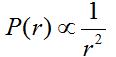
Third, the fields are proportional to L, indicated a longer dipole will radiate more power. This is true as long as increasing the length does not cause the short dipole assumption to become invalid. Also, the fields are proportional to the current amplitude  , which should make sense (more current, more power).
, which should make sense (more current, more power). The exponential term:

describes the phase-variation of the wave versus distance. Note also that the fields are oscillating in time at a frequency f in addition to the above spatial variation.
Finally, the spatial variation of the fields as a function of direction from the antenna are given by  . For a vertical antenna oriented along the z-axis, the radiation will be maximum in the x-y plane. Theoretically, there is no radiation along the z-axis far from the antenna.
. For a vertical antenna oriented along the z-axis, the radiation will be maximum in the x-y plane. Theoretically, there is no radiation along the z-axis far from the antenna. In the next section further properties of the short dipole will be discussed.
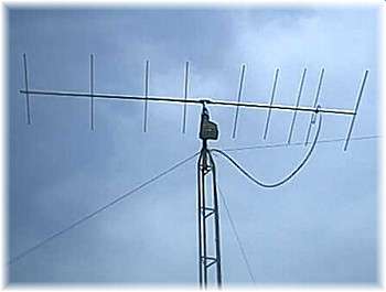
Yagi-Uda Antenna
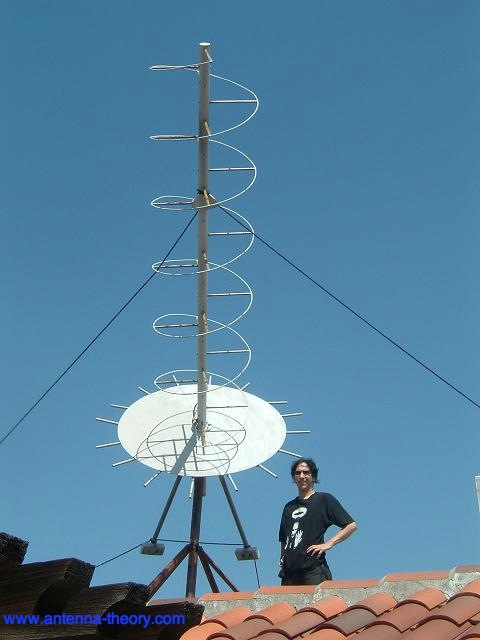
The Yagi-Uda antenna or Yagi is one of the most brilliant antenna designs. It is simple to construct and has a high gain, typically greater than 10 dB. These antennas typically operate in the HF to UHF bands (about 3 MHz to 3 GHz), although their bandwidth is typically small, on the order of a few percent of the center frequency. You are probably familiar with this antenna, as they sit on top of roofs everywhere. An example of a Yagi-Uda antenna is shown below.


Post a Comment