Subscribe To

Enter your email address:

Delivered by VS

Followers

Pages

0 Removedrive guard virus

One of our readers wanted to know the method to remove DriveGuard.exe virus which is also known by the names FlashGuard.exe and DriveMonitor.exe. So here goes the solution that is bit different from the other virus removal methods.

What DriveGuard.exe does?
•    Adds itself to startup and the task manager.
•    Adds a registry key for making changes in the registry editor.
•    Adds Autorun.inf file in the pen drive
•    Adds some malicious temporary files in the system.
Solution:
1.    Boot the computer in the Safe Mode.
2.    Open the task manager and kill the processes with names DriveGuard.exe/FlashGuard.exe/DriveMonitor.exe
3.    Open My Computer and search for the same virus names but don’t forget to check all the boxes in the ‘More Advanced Options’ of search. Delete all the files.
4.    Now search for .tmp.exe and delete DriveGuard.tmp.exe and gHmpg.tmp.exe files, if any.
5.    Open the msconfig, now go to startup processes and uncheck the FlashGuard process to remove it from the startup list.
6.    Open Regedit and navigate to HKEY_LOCAL_MACHINE\Software\Microsoft\Windows\CurrentVersion\Run\FlashGuard.

7.    Click on FlashGuard and delete the key.
The virus would have been removed.
0 Antennas

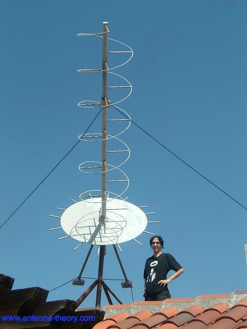
Helix antennas have a very distinctive shape, as can be seen in the following picture.

picture of helix antenna on a roof

Photo courtesy of Dr. Lee Boyce.
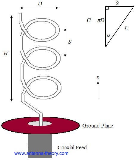
The most popular helical antenna (often called a 'helix') is a travelling wave antenna in the shape of a corkscrew that produces radiation along the axis of the helix. These helixes are referred to as axial-mode helical antennas. The benefits of this antenna is it has a wide bandwidth, is easily constructed, has a real input impedance, and can produce circularly polarized fields. The basic geometry is shown in Figure 1.

Left Hand Circularly Polarized Helical Antenna Helix Figure 1. Geometry of Helical Antenna.
The parameters are defined below.

  • D - Diameter of a turn on the helix.

  • C - Circumference of a turn on the helix (C=pi*D).

  • S - Vertical separation between turns.

  • - pitch angle, which controls how far the antenna grows in the z-direction per turn, and is given by

  • N - Number of turns on the helix.

  • H - Total height of helix, H=NS. The antenna in Figure 1 is a left handed helix, because if you curl your fingers on your left hand around the helix your thumb would point up (also, the waves emitted from the antenna are Left Hand Circularly Polarized). If the helix was wound the other way, it would be a right handed helical antenna.
    The pattern will be maximum in the +z direction (along the helical axis in Figure 1). The design of helical antennas is primarily based on empirical results, and the fundamental equations will be presented here.
    Helices of at least 3 turns will have close to circular polarization in the +z direction when the circumference C is close to a wavelength:

    circumference of helix antenna
    Once the circumference C is chosen, the inequalites above roughly determine the operating bandwidth of the helix. For instance, if C=19.68 inches (0.5 meters), then the highest frequency of operation will be given by the smallest wavelength that fits into the above equation, or =0.75C=0.375 meters, which corresponds to a frequency of 800 MHz. The lowest frequency of operation will be given by the largest wavelength that fits into the above equation, or =1.333C=0.667 meters, which corresponds to a frequency of 450 MHz. Hence, the fractional BW is 56%, which is true of axial helices in general.
    The helix is a travelling wave antenna, which means the current travels along the antenna and the phase varies continuously. In addition, the input impedance is primarly real and can be approximated in Ohms by:

    input resistance or impedance for helix antennas
    The helix functions well for pitch angles (pitch antenna) between 12 and 14 degrees. Typically, the pitch angle is taken as 13 degrees.
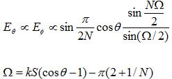
    The normalized radiation pattern for the E-field components are given by:

    radiated E-field for helical antenna
    For circular polarization, the orthogonal components of the E-field must be 90 degrees out of phase. This occurs in directions near the axis (z-axis in Figure 1) of the helix. The axial ratio for helix antennas decreases as the number of loops N is added, and can be approximated by:

    axial ratio of helix antennas
    The gain of the helix can be approximated by:

    gain of helical antenna
    In the above, c is the speed of light. Note that for a given helix geometry (specified in terms of C, S, N), the gain increases with frequency. For an N=10 turn helix, that has a 0.5 meter circumference as above, and an pitch angle of 13 degrees (giving S=0.13 meters), the gain is 8.3 (9.2 dB).
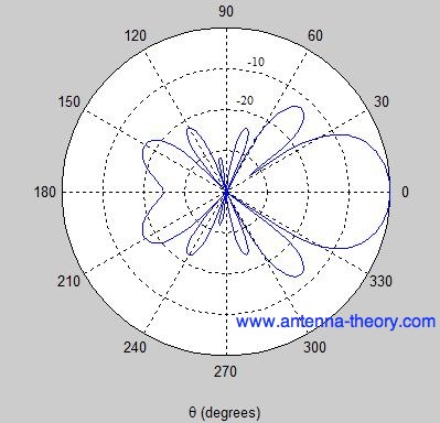
    For the same example helix, the pattern is shown in Figure 2.

    radiation pattern for helix helical antennas Figure 2. Normalized radiation pattern for helical antenna (dB).
    The Half-Power Beamwidth for helical antennas can be approximated (in degrees) by:
    HPBW for helical (helix) antenna  

    The Short Dipole Antenna


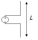
    The short dipole antenna is the simplest of all antennas. It is simply an open-circuited wire, fed at its center as shown in Figure 1.
    short dipole antenna Figure 1. Short dipole antenna of length L.
    The words "short" or "small" in antenna engineering always imply "relative to a wavelength". So the absolute size of the above dipole does not matter, only the size of the wire relative to the wavelength of the frequency of operation. Typically, a dipole is short if its length is less than a tenth of a wavelength:
    length of short dipole antennas
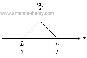
    If the antenna is oriented along the z-axis with the center of the dipole at z=0, then the current distribution on a thin, short dipole is given by:

    current distribution on short dipole antenna
    The current distribution is plotted in Figure 2. Note that this is the amplitude of the current distribution; it is oscillating in time sinusoidally at frequency f.

    plot or graph of current along a dipole antenna Figure 2. Current distribution along a short dipole.
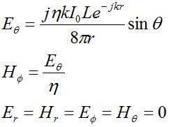
    The fields radiated from this antenna in the far field are given by:

    electric fields radiated from a short dipole antenna
    The above equations can be broken down and understood somewhat intuitively. First, note that in the far-field, only the E-theta electric field in the theta direction and magnetic field in the azimuth direction fields are nonzero. Further, these fields are orthogonal and in-phase. Further, the fields are perpendicular to the direction of propagation, which is always in the direction of propagation direction (away from the antenna). Also, the ratio of the E-field to the H-field is given by characteristic or intrinsic impedance of free space (the characteristic impedance of free space). This indicates that in the far-field region the fields are propagating like a plane-wave.
    Second, the fields die off as 1/r, which indicates the power falls of as
    far field power falls off as 1 over r squared
    Third, the fields are proportional to L, indicated a longer dipole will radiate more power. This is true as long as increasing the length does not cause the short dipole assumption to become invalid. Also, the fields are proportional to the current amplitude amplitude of current on short dipole, which should make sense (more current, more power).
    The exponential term:

    phase variation is described by the complex exponential
    describes the phase-variation of the wave versus distance. Note also that the fields are oscillating in time at a frequency f in addition to the above spatial variation.
    Finally, the spatial variation of the fields as a function of direction from the antenna are given by radiation pattern for short dipole. For a vertical antenna oriented along the z-axis, the radiation will be maximum in the x-y plane. Theoretically, there is no radiation along the z-axis far from the antenna.
    In the next section further properties of the short dipole will be discussed.

    Yagi-Uda Antenna


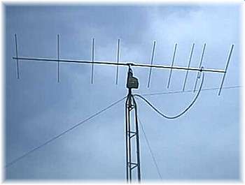
    The Yagi-Uda antenna or Yagi is one of the most brilliant antenna designs. It is simple to construct and has a high gain, typically greater than 10 dB. These antennas typically operate in the HF to UHF bands (about 3 MHz to 3 GHz), although their bandwidth is typically small, on the order of a few percent of the center frequency. You are probably familiar with this antenna, as they sit on top of roofs everywhere. An example of a Yagi-Uda antenna is shown below.

    picture of Yagi antenna
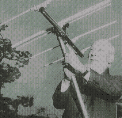
    The Yagi antenna was invented in Japan, with results first published in 1926. The work was originally done by Shintaro Uda, but published in Japanese. The work was presented for the first time in English by Yagi (who was either Uda's professor or colleague, my sources are conflicting), who went to America and gave the first English talks on the antenna, which led to its widespread use. Hence, even though the antenna is often called a Yagi antenna, Uda probably invented it. A picture of Professor Yagi with a Yagi-Uda antenna is shown below.
    inventor of the Yagi-Uda antenna, Professor Yagi
    In the next section, we'll explain the principles of the Yagi-Uda antenna.


  • 0 Helix Antenna

    Helix antennas have a very distinctive shape, as can be seen in the following picture.


    picture of helix antenna on a roof


    Photo courtesy of Dr. Lee Boyce.
    The most popular helical antenna (often called a 'helix') is a travelling wave antenna in the shape of a corkscrew that produces radiation along the axis of the helix. These helixes are referred to as axial-mode helical antennas. The benefits of this antenna is it has a wide bandwidth, is easily constructed, has a real input impedance, and can produce circularly polarized fields. The basic geometry is shown in Figure 1.


    Left Hand Circularly Polarized Helical Antenna Helix Figure 1. Geometry of Helical Antenna.
    The parameters are defined below.

  • D - Diameter of a turn on the helix.


  • C - Circumference of a turn on the helix (C=pi*D).


  • S - Vertical separation between turns.


  • - pitch angle, which controls how far the antenna grows in the z-direction per turn, and is given by


  • N - Number of turns on the helix.


  • H - Total height of helix, H=NS. The antenna in Figure 1 is a left handed helix, because if you curl your fingers on your left hand around the helix your thumb would point up (also, the waves emitted from the antenna are Left Hand Circularly Polarized). If the helix was wound the other way, it would be a right handed helical antenna.
    The pattern will be maximum in the +z direction (along the helical axis in Figure 1). The design of helical antennas is primarily based on empirical results, and the fundamental equations will be presented here.
    Helices of at least 3 turns will have close to circular polarization in the +z direction when the circumference C is close to a wavelength:

    circumference of helix antenna
    Once the circumference C is chosen, the inequalites above roughly determine the operating bandwidth of the helix. For instance, if C=19.68 inches (0.5 meters), then the highest frequency of operation will be given by the smallest wavelength that fits into the above equation, or =0.75C=0.375 meters, which corresponds to a frequency of 800 MHz. The lowest frequency of operation will be given by the largest wavelength that fits into the above equation, or =1.333C=0.667 meters, which corresponds to a frequency of 450 MHz. Hence, the fractional BW is 56%, which is true of axial helices in general.
    The helix is a travelling wave antenna, which means the current travels along the antenna and the phase varies continuously. In addition, the input impedance is primarly real and can be approximated in Ohms by:

    input resistance or impedance for helix antennas
    The helix functions well for pitch angles (pitch antenna) between 12 and 14 degrees. Typically, the pitch angle is taken as 13 degrees.
    The normalized radiation pattern for the E-field components are given by:

    radiated E-field for helical antenna
    For circular polarization, the orthogonal components of the E-field must be 90 degrees out of phase. This occurs in directions near the axis (z-axis in Figure 1) of the helix. The axial ratio for helix antennas decreases as the number of loops N is added, and can be approximated by:

    axial ratio of helix antennas
    The gain of the helix can be approximated by:

    gain of helical antenna
    In the above, c is the speed of light. Note that for a given helix geometry (specified in terms of C, S, N), the gain increases with frequency. For an N=10 turn helix, that has a 0.5 meter circumference as above, and an pitch angle of 13 degrees (giving S=0.13 meters), the gain is 8.3 (9.2 dB).
    For the same example helix, the pattern is shown in Figure 2.

    radiation pattern for helix helical antennas Figure 2. Normalized radiation pattern for helical antenna (dB).
    The Half-Power Beamwidth for helical antennas can be approximated (in degrees) by:
    HPBW for helical (helix) antenna


  •  
    © 2010 Mr. Saravanan's Blog is proudly powered by Blogger